GENIUS
REGULATION
A detailed explanation for those who want to know it exactly.
The world’s most proven method
For a wind turbine that meets the premises of medium technology, the simplest, most widespread and proven method of wind turbine control is the most suitable: namely, the combination of control and side vane. It has been used hundreds of thousands of times since the 18th century.
Tasks of the regulation
This regulation fulfills three important tasks: One is to keep the rotor perpendicular to the wind during normal operation, and another is to protect it from damage when there is a lot of wind.
- The normal operating condition, in which the generator delivers power up to just above the rated power
- The strong wind condition, where the wind offers more energy than the generator can absorb
- The “survival state” in case of storm.
Here the principle of this control procedure shall be presented in an easily understandable way
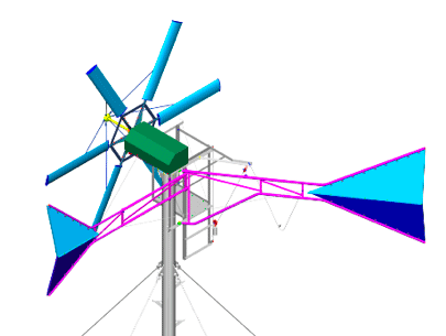
Normal operating position KUKATE
Wind pressure force, control and side vane surfaces, lever arms and control weight work together
1
Normal operation
In normal operation, the wind should hit the rotor exactly from the front. The side vane arm is fixed to the nacelle, while the control vane arm pivots with a very sturdy joint. This joint and the guide rollers for the control weight are the only moving parts of the entire control system.
If you look at the control vane from the rotor, its arm has swung out about 45 degrees from the axis direction.
The drag forces of the flag surfaces generated by the wind multiplied by the respective effective lever lengths form two opposing torques.
In normal operation, the rotor axis should be exactly parallel to the wind. The wind comes from the front.
To ensure this, the two torques in opposite directions must cancel each other out until the full rated generator output is not exceeded by more than 10% on average over a longer period of time.
2
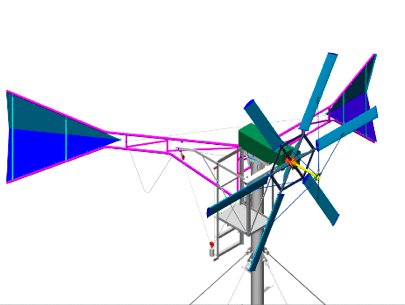
Strong wind condition
In high wind conditions, the blades, gearbox and generator would be overloaded if the wind continued to blow perpendicular to the rotor plane.
From a certain wind speed on, the tractive force in the cable of the control weight can no longer maintain the “lead angle” of the control vane arm of 45 degrees.
The weight is connected to the control vane arm by a rope and pulleys. Due to the strong wind pressure on the control vane, the weight is lifted. The control vane swings toward the side vane.
The angle between the flags decreases. The cross vane is firmly attached to the nacelle. The angle of originally 135 degrees between the two flag arms becomes smaller.
The smaller the angle between the vanes, the more the rotor swings from its normal direction.
If the wind pressure decreases, the weight “pulls” the control vane back to the old position and the wind comes from the front again.
3
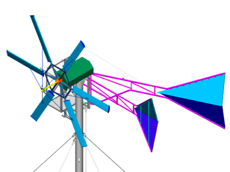
Storm case
In the event of a storm, the goal is to protect the plant from damage.
In order not to overload the KUKATE, the wind should hit as small an area as possible. This is the case when the rotor and the vane surfaces are exposed to lateral flow.
The wind pushes the two rule flags together to an angle of 30 degrees during storms. The angle is determined by a stop on the cross flag arm. The control vane arm then rests against the stop at an angle of 30 Gad between the vane arms. Then the system is in its storm-proof position.
If the wind pressure now decreases, the restoring moment from the control weight force and the effective lever arm length at the control vane arm is greater than the moment generated by the wind at the control vane. It is more or less pulled back to its starting position, the rotor again gets the wind increasingly from the front.
Adjusting the control
Every plant operator can easily change the behavior of the control. He can vary the weight forces and “attachment points of the control weight ropes” on the nacelle or on the control vane arm. The same applies to the initial angle of spread of the rope above the sheave.
If the weight rope breaks, the system automatically swings into the storm position. The control is thus “intrinsically safe”.
The best for the KUKATE
The control method using control and side vane is factually unbeatable for small wind energy converters like the KUKATE34.
You can easily build it yourself, it is manageable and safe – in short: It meets all the requirements of the “medium technology” preferred here: No pneumatics, hydraulics and electronics!
Different reset forces possible
The restoring forces that swing the system into the positions can be generated differently by
- a single vertically suspended control weight and a deflection pulley
- or via a V-shaped suspended control weight and two deflection pulleys (mostly used for the KUKATE)
- a spring suspended between the control vane and the guy arm
A simple control weight on a deflection pulley generates, in a first approximation, a constant and a control spring, a return force of the control vane that increases in proportion to deflection.
The v-shaped weight suspension with two rollers generates a restoring force that increases progressively with the angle of deflection of the vane. This desirable customizable control is a game changer – without abandoning mid-range technology.
With the v-shaped weight control, a characteristic curve adjustment option is available for professionals. It reacts very sensitively and still works reliably. The greater the v-shaped angle between the ropes from which the weight roller hangs, the harder the control reacts.
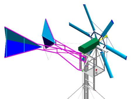
The two films show the dynamic control behavior of the control and side arm control:
The regulation of “turning out of the wind” with control vanes:
The regulation of “turning out of the wind” with control vanes with simple weight suspension:


