KUKATE
Rotor concepts
Preliminary remarks: These rotor concepts are not part of our exact building instructions as we present them on this OPEN WINDMILL website for the KUKATE34 piston pump.
However, they are a treasure for anyone who wants to succeed with a homemade wind rotor.
No special engineering or aerodynamic knowledge is required. Any metal craftsman will be successful if he adapts our design proposals to his specific needs.
Three different rotor concepts for do-it-yourself construction
They can be easily replicated and are designed for use in developing countries.
By publishing the manufacturing documents, we enable their worldwide replication.
An additional classification of the individual rotor concepts clarifies the specific advantages as well as disadvantages of a concept.
With this offer we enable the pre-selection of the suitable rotor type. This ensures an optimal realization adapted to the needs.
Dimension rotor yourself
The rotor of a wind turbine is undoubtedly the most important component that has to convert the energy from the air flow of the wind into technically usable power.
If you want to dimension a rotor yourself, you can do so according to the instructions of Professor Dr. Horst Cromes. In his “Handbuch Windenergie Technik” – chapter 5.4. “Rotor design in a nutshell” in eight steps – described how it is done. Those who follow this “recipe” will get the results they need for their requirements.
1
Canvas rotor
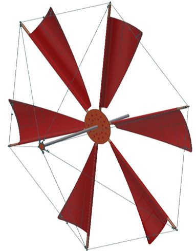
Six-bladed sailcloth rotor modeled on sailing windmills – that is, using sails made of cloth.
Advantage: It is easy to vary and repair. The design itself also prevents overloading in the event of a storm.
2
RoWiTool-Rotor
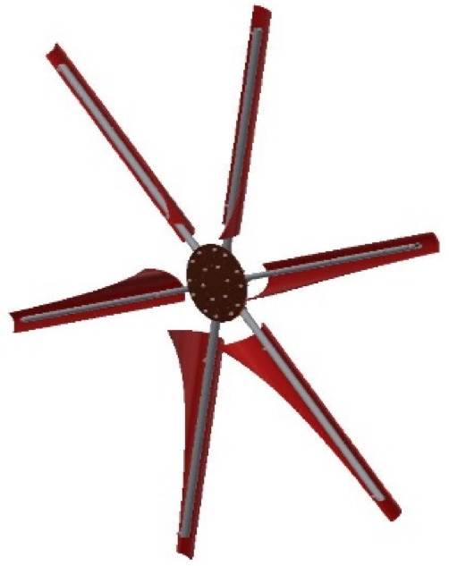
RoWiTool is a freely accessible, table-based program that can be used to generate a template for manufacturing a rotor blade.
Together with the basic design elements of the rotor of the KUKATE34, rotors for various applications can be designed, built and operated.
The starting material for the rotor blades is usually plastic tubes. After cutting, its round outer contour forms the aerodynamic suction side of the wing profile.
3
KUKATE34-rotor
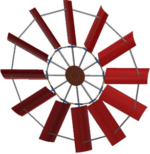
The rotor blade we use to power our KUKATE wind turbines.
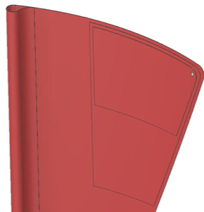
It consists of water pipe spars and twelve rotor blades made of curved sheet metal.
This ingeniously simple and easy-to-build design behaves amazingly effectively from an aerodynamic point of view and is ideal for our purposes.
We use such rotor blades for all KUKATE34 rotors. Self-builders can realize drives for any purpose with this twelve-bladed wind turbine.
Sail windmill rotor
The high-tech rotors of modern large wind turbines tend to draw the eye of millwrights to very streamlined rotors. If electrical power is to be generated, a high-speed number of at least 5 is also aimed for. For such applications canvas rotors are usually not the 1st choice.
They rotate 40 to 100 times a minute. The KUKATE sail rotor has a high-speed factor of 2.2 For power generation, a gearbox must then usually be installed between the rotor shaft and the generator shaft to increase the speed.
Unfortunately, even do-it-yourself water pump builders have often shelved the many advantages of old rotor designs. That’s not what we at OPEN WIND want here. We are already looking forward to the experience and success stories of operators who build and operate canvas wind turbines.
With the following we describe first how they are built and then at the end why they are so advantageous.
Different materials are suitable for the use of the sailcloth, such as foils, car tarpaulins or even textile fabrics.
Thus, no specific material for the sails is specified in the manufacturing documents, especially in the parts lists. The trapezoidal or triangular sails are sewn from several sheets in such a way that they are pushed or sucked by the wind to form a bulbous lift profile.
The air inflow, which is composed of the rotational speed and the wind, curves them into an effective lift profile.

A sail windmill does not have rotor blades of the usual design mounted. The torque of the rotor is generated by means of sails. These are placed in front – windward – on spars made of wood or metal The renewable raw material wood plays a very important role in traditional mill construction. In addition to wood from ash, oak wood has proven itself for the spars.
At the rear end (for sailors: the clew), the cloth sections are attached to the circumferential rope and are thus as taut as ship sails in operation. There are many adjustment options depending on the application and wind.
If you choose a rubber band for the connection from the clew to the circumferential rope, it will tighten more and more as the speed of rotation increases due to the buoyancy force. Above a certain elongation length of the rubber band, the flow breaks off because the angle of attack is then too steep and the rotor does not speed up. This is a perfect automatic stall control!
In order to extend the modularity of the individual rotor concepts, we base the design of the sail windmill rotor on the rotor hub already used in our other rotor concepts. We adapt these constructively in such a way that a shaft with the diameter of 40mm can be passed through in the center.
The construction of the entire rotor is composed of the modified rotor hub, spars, sails and their guys.
For the design, we first made assumptions, which are in the following table.
Acceptance
Rotor diameter:
3.4 [m]
Rotor diameter:
0.25 [-]
Number of sheets:
6 [-]
Angle of attack:
17 to 25 [°]
Camber ratio of the sails in operation:
1:10 to 1:20 [-]
Fast Run Number:
approx. 2.2 [-]
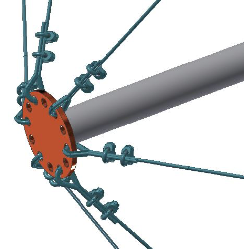
It is placed on the shaft and connected with two 10 mm thick screws inserted through the hub and shaft or also with suitable clamping sleeves. The individual rotor spars are attached to the hub disk by screw connections via pipe clamps. The rotor spars are connected to each other and to the rotor shaft by bracing to prevent vibration of the rotor during operation. The guy wires are made of 3-4 mm thick steel wire, which is tensioned and fixed by means of standardized wire rope clamps
Unlike in the illustration, the rope ends must be fastened with 4 rope clamps on each side after the thimble!
This is especially important for stainless steel wires. They are smooth as soap and slip easily. The rope clamps should have at least M6 clamping brackets.
Different materials are suitable for the canvas, such as foils, car tarpaulins or even textile fabrics. In the production documents, especially in the parts lists, we therefore do not prescribe any specific material for the sails. The trapezoidal or triangular sails must be sewn from several sheets in such a way that they are pressed or sucked by the wind to form a bulbous lift profile. The air inflow, which is composed of the rotational speed and the wind, then bulges the cloth into an effective lift profile during operation.
If we make the rear bracing of the sails from rubber bands – you can also take steel cables with steel springs mounted in the strand in between – the rotor will be self-securing!
Once the rotor has reached its rated power, the guy wires increasingly stretch towards the leeward side due to the increasing suction. The airflow applied during operation then tears off and swirls at the trailing edges of the sails. The resulting turbulence limits the speed in a desirable way. Built-in security is what we call this.
These rotors are suitable for many needs. In very strong winds, you can simply remove three sails. But even otherwise there are a considerable number of variants to experiment with.
But even otherwise there are a considerable number of variants to experiment with. They generate a large torque during start-up and low wind speeds. This is very desirable for the pump, since the static friction must first be overcome from standstill.
As the wind increases, the wing depth on the outside – compared to the aerodynamic ideal profile – is too large and the pump is spared. If the wind gets even stronger, it has a total of three safety systems:
- The stalling flow in the outer rotor area in case of (too) strong wind due to the then too large wing depth at the ends.
- The rear guy wires stretching in high winds, causing the current to break off.
- The side and control vane control, which turn the rotor out of the wind during storms.
We at Green Desert are already eagerly awaiting successful experience reports, which we will gladly pass on with your suggestions for changes and improvements.
KUKATE34K
Wind pump
> Building instructions:
- Introduction
- 0. Preparation
- 1. Mast
- 2. Gondola
- 3. Control unit
- 4. Pump
- 5. Foundation
- 6. Final assembly
- Building instruction KUKATE34K
> Technical drawings
KUKATE34M
Membrane pump
> Technical drawings
KUKATE
Rotor concepts
> Building instruction KUKATE34 rotor
> Building instruction KUKATE34R rotor
> Building instruction KUKATE34S rotor
The drawings and parts lists are included in the respective assembly instructions.
> Construction manual
> Parts list
> Technical drawings
