GENIUS
ROTOR CONCEPT
For those colleagues who want to know more.
The rotor concept described on this page convincingly illustrates the simplification of the theoretical “ideal wing” to the technically reasonable wing of the proven KUKATE type.
The contents assume basic aerodynamic knowledge.
Please remember: A small wind energy converter is not a “small big one”!
Very good simplifications are possible with smaller rotors.
Note: In my “Handbook of Wind Energy Technology” I have described in sections 5.3. “The technically reasonable wing” and 5.4 “Rotor design in a nutshell”, which I can only briefly explain here.
Preliminary considerations for the KUKATER rotor concept:
Three pragmatic aspects
Now follow three steps of thought. The first deals with the amount of material to be used for the wings. The second step deals with the “harvest area” (This is the area swept by the rotor. It is from this area that the rotor blades extract the energy from the airflow).
The third idea deals with the perfectly acting twist of the wing profile from the hub to the end of the wings.
1
Material costs for the wings
Aerodynamically reasonable and 85% material saved
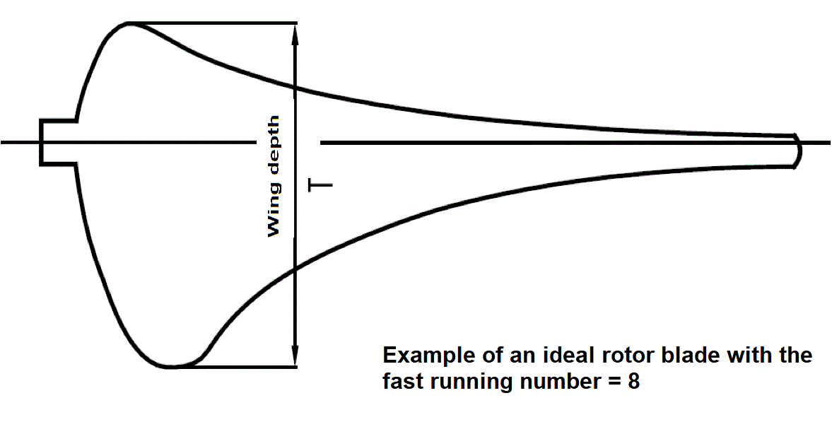
A theoretically aerodynamically optimal rotor profile is wide and thick at the root (in the hub area) and narrow and slim at the tip. (This dimension is called the “wing depth” T )
Consideration: Let’s mentally divide the length of the rotor blade from the hub to the end of the blade in the middle of the length into two parts of equal length.
We thus obtain an inner half and an outer half. Now let’s look at the material and therefore the cost and weight of the two half wings on the graph.
Aerodynamic theory
For aerodynamic reasons (low flow velocities, short levers), an ideal wing would require about eight times more structural mass in the inner half of the wing than in the outer half. Only then will the wind power in this inner area quarter (!!!) be well “harvested” by the blades. Nice if the KUKATE rotor principle saves there.
RESULT: The graphic shows a “theoretical-ideal wing”.
As can be seen, the material and thus the cost and weight requirements for the inner half of an “ideal” rotor are many times higher than those for the outer half.
2
The effective harvested area
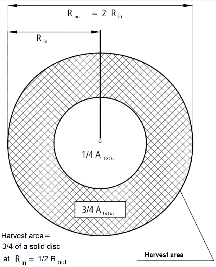
As the circular disk illustrates, the inner halves of the rotor’s blades sweep only a quarter of the crop area, but the outer halves sweep three quarters.
Facts:
- All rotor blades sweep only 1/4 of the crop area with their inner half.
- They are usually not aerodynamically optimally designed towards the center for technically and economically sound reasons.
Conclusion for the KUKATE principle: The OPEN WIND KUKATE rotors have no profile inside. They therefore save large wing masses in the inner crop area, which is uninteresting for performance.
Therefore, the KUKATE rotors have a circular ring as the harvesting surface. With the sash profiles on the outside, the effective levers are longer and the flow around the sash is faster than on the inside.
The storm load is also much lower if large-area material is not used in the area of the rotor center.
3
The torsion
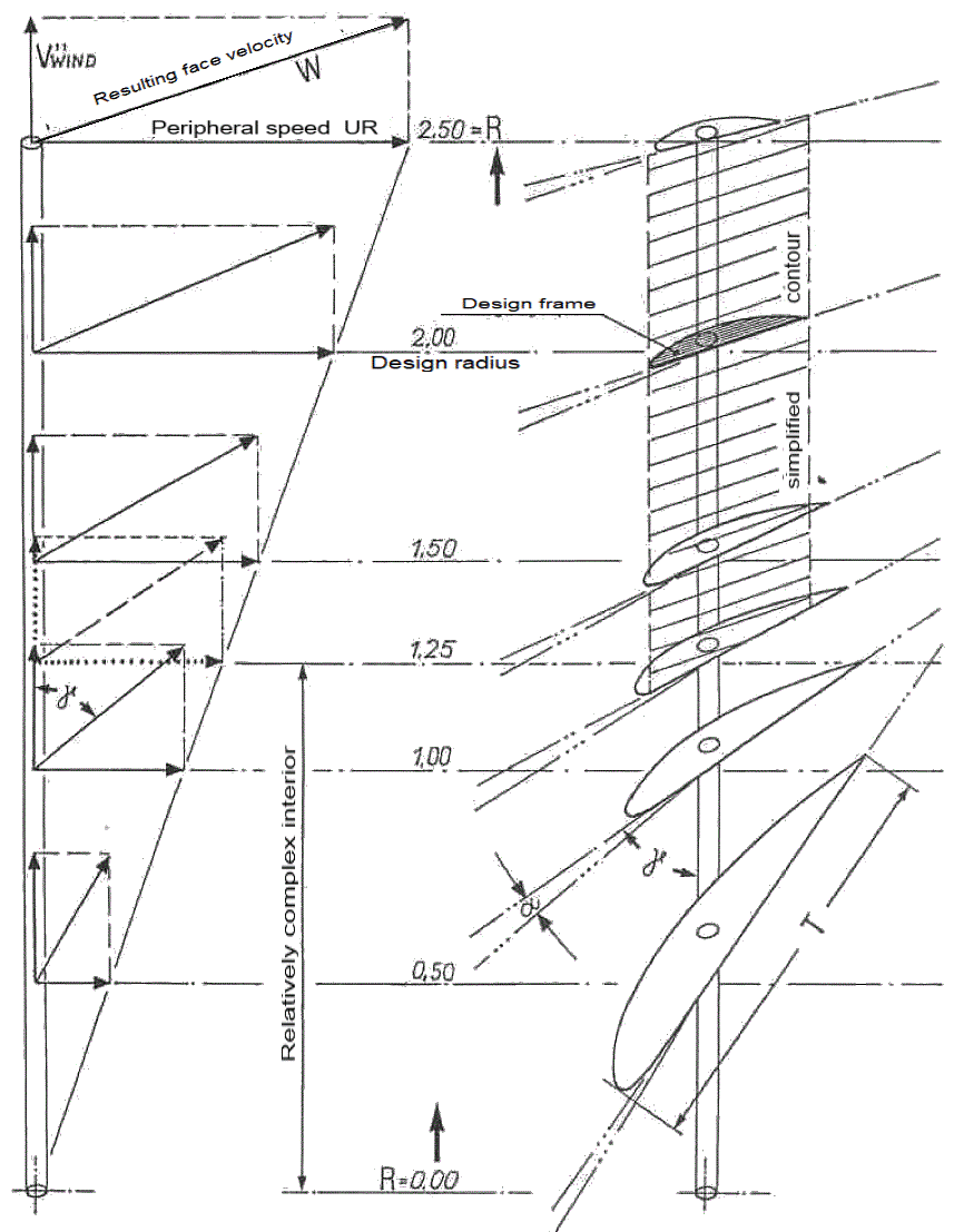
As a third step for an “ideal” rotor design, the different directions of airflow onto the rotor blade have to be considered.
The resulting different angles of attack of the wing from the hub to the tip are the result of theoretical preliminary considerations by the designer.
When designing a specific rotor, the designer must make three decisions: First, he must determine the high-speed number, second, the so-called “design wind speed” and third, the number of blades.
As a result, a blade depth and a twist angle at a certain point of the rotor blade are then obtained for this individual case.
In fact, a concretely designed rotor with twisting rotor blade and variable airfoil depths is ideal for only one “design wind speed”. The designer must decide which one to use. At all other wind speeds, losses from the maximum possible are inevitable.
The graph shows the simplification from the ideal wing at one wind speed to the rectangular non-torqued “half-wing” of the KUKATE design (shaded rectangular area with the design bulkhead on the upper right).
From the complex to the simple:
End of the preliminary considerations
The KUKATE rotor concept we have developed differs from a theoretical ideal design in three respects:
- The wing depth does not change.
- The wing sweeps an effective (outer) circular ring crop area as a half-wing.
- The sash profile remains without torsion angle over the entire length.
Theory and practice
To repeat: The rotor blade built with different profile depths and twists is “correct” only for a single “punctual” wind flow velocity.
This only occurs for seconds in practical operation.
At all other speeds, the optimal calculated power extraction of the “ideal blade” decreases, because then all assumptions over the entire rotor blade length are no longer accurate.
The ingenious trick of the KUKATE rotors is thus justified as follows:
The aerodynamic advantages for simplification
A rotor blade whose profile does not change in depth and is not twisted has advantages.
Practical tests have shown that power extraction becomes maximum when the calculated optimum angle of attack and the calculated wing depth for the airfoil are correct at 5/6 of the total rotor blade length.
Then the rotor is even self-regulating in a wide wind speed range.
The power draw and the angle of attack at the speeds then present are then well adapted to the application.
- Lower wind speed than for the design:
The outer area of the surface swept by the rotor is then used most optimally at lower than the (design) wind speed. The rotor starts up easily.
The optimal harvesting area is large on the outside, and the effective levers are long. This is desired. - Higher wind speed than for the design:
If the wind speed reaches values that would overload the pump or generator, the KUKATER rotor “relocates” its optimum fluidic effect to the inner area without the wind flow breaking off along the entire length of the profile at once. If gusts are strong, the current first tears off at the then “incorrectly” set blade tips and thus protects the construction. Because then the buoyancy forces there will be lower. The efficient harvesting area then also becomes smaller and the lever arms are shorter. This is desired.
The passive rotor automatic
Thus, the rotor can automatically adapt well to the characteristic curve of a generator or pump in a wide operating range. At high wind speeds, the control and side vane regulate the desired power extraction.
Passive self-regulation and passive self-assurance is what we call this.
In strong winds, the wind-loaded rotor surfaces and thus the wind forces remain optimally small.
Small deviations from the ideal wing
The power loss of the “technically reasonable wing KUKATE” determined according to our measurements is about 15% of the optimal ideal wing.
Easy to compensate
If you want the “ideal” performance, you can increase the diameter of the KUKATE rotor only by 10%! In any case, our KUKATE34 rotor with 3.4 m diameter with the simple sheet metal profiles has slightly more power than an ideal wing rotor with 3 m diameter.
The ingenious trick: no profile towards the hub, a constant wing depth and no torsion.

Here is a KUKATE single wing made from a 1:10 curved sheet rectangle of 5 mm thick aluminum. In developing countries, a practical realization possibility.


