KUKATE34K
Wind pump
Making the production of all components as simple as possible was the special challenge with the KUKATE34K
The plants are to be manufactured in elementary equipped workshops from easily procurable material made of steel.
This means that welding equipment and lathes and pillar drilling machines can be assumed, but not special tools such as milling machines.
If they are available, they can be used when appropriate. Therefore, already during the construction, attention was paid to a simple implementation.
Understanding made easy
For those who want to know more, here we explain a bit more how the standard OPEN WINDMILL rotor was designed.
The rotor diameter must be designed according to the desired pump capacity. This amounts to 1 l/s from a
Conveying depth Δℎ of 10 m.

This results in a pump power P of 100 W.
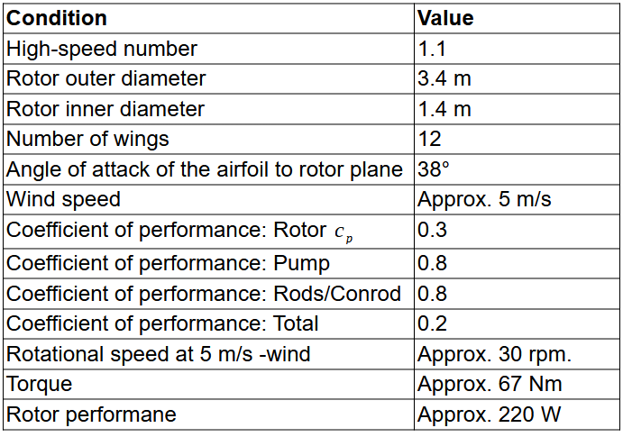
The pump power is not the power of the rotor due to the losses. Here, the efficiencies of the pump (ŋ=0.8), the linkage (ŋ=0.8) and the rotor (ŋ=0.3) must be used to calculate the necessary power.
The overall efficiency is the product of the individual efficiencies:

The shaft power of the rotor as feeding power must be:

According to this calculation, a wind power of 500 W is required. With an average wind speed of 5 m/s, the required rotor diameter can be determined. It is known from the literature that 75 W of power is contained in the wind per square meter. Our KUKATE34 rotor can convert 30% of this into rotor shaft power (ŋ=0.3).
The required rotor area must be:

This results in a necessary area of 6.6 m² to generate the 500 W power. However, the rotor at hand does not have continuous rotor blades and thus a circular ring with an outer diameter of 3.4 m and an inner diameter of 1.4 m is created. Thus, the harvesting area of the rotor is slightly above the value of 6.6 m² and it can produce slightly more than 500 W at 5m/s wind.

In the section KUKATE34Rotor (rotor only) and KUKATE34K34Windpump (piston pump) you can download the construction plans for free. We will be concrete there to the last screw.
Function
Implementation
General
Structure:
Modular, site assembly
Lifetime:
> 20 years
Control:
Control and side vane control weight
Start-up speed:
light wind (approx. 3 m/s)
Control regulates down at:
7–9 m/s
Transportability:
max. 6 m long components
of people to transport
Recyclability:
almost 100%
Surface treatment:
Anti-rust paint / coating
Mast
height
(6 bis) 10 m
Mast construction
four mast stems, truss, L-profile,
Base 1.5 m, head 0.3 m, foldable
Foundation
Sleepers or concrete
Gondola
Nacelle weight + rotor + flags
max. 200 kg
Shaft diameter
40 mm
Shaft bearing
Pedestal bearing
Gondell storage
Plain bearing
Rotor
Incoming flow
Luv
Number of wings
12
Rotor diameter
3,4 m
Wing material
Sheet steel / aluminum 1.5 / 3 mm
Profile shape
curved plate 1:10 to 1:8
High-speed number
1,1
Nominal wind speed
5 m/s
Security
Hurricane-proof up to 60m/s
safe against hail, lightning protected
Pump
Design pump height Piston pump
10 m
Pumping capacity at 6 m/s wind
Min 3600 l/hour at 10 m delivery depth,
corresponding to over 86000 l per day
Shaft power
220 W at 5 m/s 700 W at 7 m/s
Reliability
All wear parts can be produced by the customer and quickly replaced
History of the KUKATE34
History: Largest test field in Europa
Professor Dr. Horst Cromes more than thirty years of experience in the development, self-construction and operation of wind turbines on his own test field is unique in the world.
For more than 20 years, he and his team operated the largest test field for do-it-yourself systems in Europe. More than 40 diploma theses, bachelor and master theses were aimed at the design, testing and optimization of the KUKATE wind energy converters.
The young designers took into account in their work the experience gained from the operation of over one million wind pumps currently in use worldwide. They have rotor diameters from 2m to 7m and rotor blade numbers from two to twelve.
Their use is mainly for power generation in developing or emerging countries. We transfer the simple and robust design of these types of equipment to the OPEN WINDMILL pump KUKATE34.
Career:
- Theoretical conception 2014 – 2016
- Theoretical conception 2014 – 2016
- Mounting and assembly with the help of BeLu 2017
- Compilation of construction instructions, technical drawings, material and tool parts lists from 2017.
Autonomous water supply worldwide
Overall, the KUKATE34 project is unique in the world at this level and complexity and can be used to address many thousands of autonomous water supply problems using renewable wind energy. Helping people to help themselves is the top priority for the OPEN WINDMILL working group.
Metal workshop and basic knowledge are enough
It was therefore a particular challenge in this project to make the production of all components as simple as possible. Therefore, already during the design phase, attention was paid to a simple construction. The equipment can be manufactured in elementary equipped workshops from easily procured materials.
Read also:
KUKATE34K
Wind pump
> Building instructions:
- Introduction
- 0. Preparation
- 1. Mast
- 2. Nacelle
- 3. Control unit
- 4. Pump
- 5. Foundation
- 6. Final assembly
- Building instruction KUKATE34K
> Parts list
> Technical drawings follow
KUKATE34M
Membrane pump
> Building instruction follows
> Parts list follows
> Technical drawings follow
KUKATE
Rotor concepts
> Building instruction follows
> Parts list follows
> Technical drawings follow
> Construction manual
> Parts list
> Technical drawings
